Do Resistors Have a Max Voltage? Ratings Explained
Do resistors have a max voltage? Yes. Every one carries a ceiling above which the film cooks, drifts, or flashes across itself. That limit is not stamped on the body. It emerges from three overlapping factors: wattage rating, physical dimensions, and internal architecture. Tiny surface-mount chips give way first. Bulky through-hole axials and dedicated high-voltage builds shrug off much more.
Last updated: August 13, 2026. Rewrote the physics section, tightened the vocabulary, added a derating table and worked bench example.
Do Resistors Have a Max Voltage in Real Circuits?
They do, and the reason is stubbornly physical. A resistive element converts current into heat. Shove enough potential across it and two separate failures line up. The first is thermal: dissipated power climbs past what the body can shed, and the coating scorches. The second is dielectric: the field itself punches through the film or arcs between the end caps. Whichever happens sooner is what actually kills the component.
Two ceilings, then. One depends on how well the package sheds heat, so it moves with wattage and resistance. The other is the datasheet figure labeled “maximum limiting element voltage” or “working voltage,” and it is a straight electrical breakdown number. Your usable headroom is the lower of the pair. Miss it and you get char, drift, or a sudden pop.

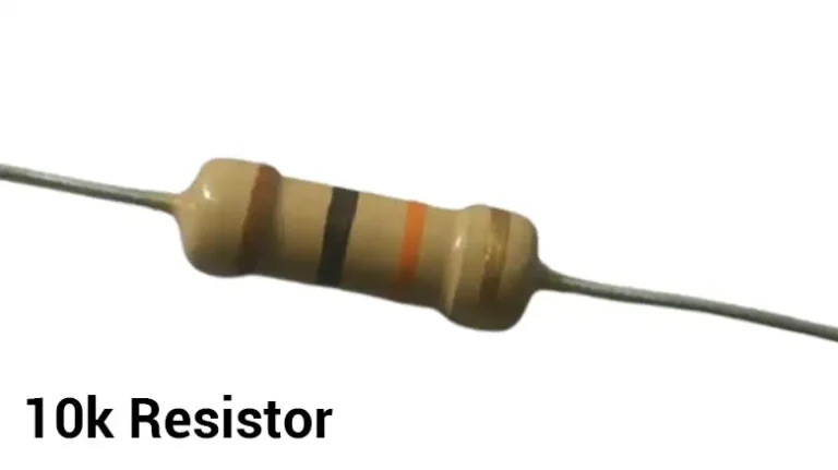
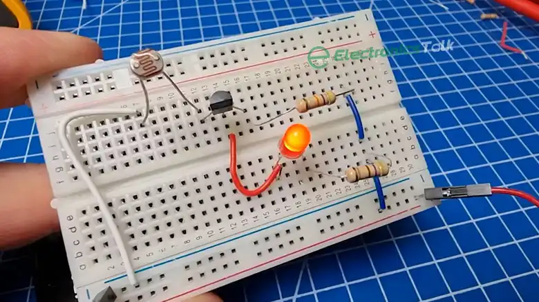
Figure 01: Resistors
What Sets the Ceiling
Four ingredients shift the answer up or down. None acts alone. Manufacturers weigh all of them together when they publish a rating, so pull the datasheet for the specific resistor rather than trusting a rule of thumb.
- Wattage class. A quarter-watt film sheds less heat than a 2 W body, so its thermal ceiling arrives sooner. Larger dissipation, taller headroom.
- Body length and material. Longer packages separate the end terminals farther apart, giving the field more distance to jump. A 1206 chip beats a 0603 by a wide margin for exactly that reason.
- Coating and encapsulation. Quality conformal coatings resist surface arcs. Cheap epoxy lets creep tracks form and eventually flash over.
- Element geometry. Purpose-built high-voltage devices use spiral trims or long meander paths that spread the electric field and suppress corona discharge. That engineering is most of what you pay for.
Notice ohmic value is absent from the list. A 10Ω and a 10MΩ device in the same case share the same rated working voltage. What shifts is which limit you strike first, and the arithmetic below explains why.
How to Find a Resistor’s Maximum Voltage
Here is the exact procedure I run. Under a minute per component.
- Read the wattage (Pmax). Marked on the body or listed as 0.25 W for a common quarter-watt axial.
- Read the ohmic value R. Say 10,000 Ω.
- Compute the thermal ceiling. Rearrange P equals V squared over R into V equals the square root of (Pmax times R). Here, root of (0.25 x 10,000) equals 50 V.
- Look up the datasheet working voltage. A small axial typically spans 200 to 500 V for dielectric breakdown.
- Take the smaller figure. In this scenario 50 V wins, so that becomes your real cap.
- Derate for margin. Aim near 70% in steady-state operation. Your usable envelope drops to roughly 35 V, and the film stays cool.
Watch how ohms flip the outcome. Keep the same 0.25 W spec but drop R to 100 Ω. Now the thermal ceiling equals the square root of (0.25 x 100), which is only 5 V. Identical package, identical wattage, one tenth the safe span. That is the trap folks fall into when they grab a component from a junk drawer without checking.
Voltage Rating by Resistor Type
Rough working numbers below, not exact specs. Confirm against the actual datasheet, because vendors can differ by a factor of 1.5x or more.
| Resistor type | Typical body length | Typical max working voltage |
|---|---|---|
| SMD 0603 chip | 1.6 mm | 50 V |
| SMD 0805 chip | 2.0 mm | 150 V |
| SMD 1206 chip | 3.2 mm | 200 V |
| Through-hole carbon film, 1/4 W | 6.3 mm | 200 to 350 V |
| Metal film axial, 1/4 W | 6.3 mm | 250 to 500 V |
| High-voltage thick film | large body | 3 kV and up |
The pattern is obvious. Length buys headroom. If your design needs to withstand a few kilovolts, reach for a purpose-built HV device, or wire several ordinary units in series to divide the stress. Two 250 V pieces stacked share the burden and yield a 500 V string.
How I Check It on the Bench
In my experience the datasheet is right and my memory is wrong, so I look it up every single time. Once I dropped a batch of 0603 chips onto a 120 V rail and half of them drifted within a week even though the thermal math said they were fine. The dielectric limit, not heat, wrecked them. Lesson learned. Now I fit 1206 pieces or larger anywhere the bus climbs above 50 V, and I never trust a micro-chip near mains. Do not skip the working-voltage row on the datasheet. That figure bites you quietly, months after the build ships.
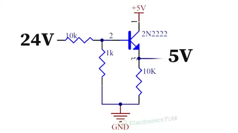
If you want to see how a component can shift on you over time, aging effects on resistor value covers the mechanisms, and the related question of whether carbon parts degrade walks through common failure modes. Thermal and dielectric stress both accelerate those problems, so extra headroom buys you lifespan. If your build already runs warm, why LED current-limiters heat up explains the same power dynamics from a different angle. For anyone stepping voltages down before the resistive stage, reducing 24 V to 5 V through a divider walks through the math end to end.
A Worked High-Voltage Example
Say your board rails a 400 V DC bus into a monitoring divider, and you need something under 1 mA of leakage. Grab a 470 kΩ metal film axial. Thermal ceiling equals root of (0.25 x 470,000), roughly 342 V. The datasheet working voltage for that body is around 350 V. Both figures sit near your 400 V demand, so a single piece is unsafe. Stack four in series instead: each unit sees roughly 100 V, well below either cap, and total dissipation spreads across four bodies. Series strings solve almost every high-voltage divider headache this way.
Frequently Asked Questions
What happens if I exceed the max voltage on a resistor?
The film can overheat, drift out of tolerance, or arc between the end caps. In a bad case it burns open and damages neighboring circuitry. If the failure mode is dielectric breakdown rather than slow cooking, it can happen in a fraction of a second.
Do resistors have a max voltage that depends on resistance?
The dielectric rating does not. That figure is fixed by the package geometry. But the thermal ceiling absolutely depends on ohms, since V equals the square root of (Pmax times R). Your true cap is the smaller of the two, so a high-ohm device inside a tiny case is usually breakdown-limited.
Can I just add cooling to raise the voltage limit?
Cooling helps the thermal side, so it lifts your dissipation-driven ceiling a little. It does nothing for dielectric breakdown, which is baked into the build. Choose a component rated for the job rather than trying to chill your way around the physics.
How do I get a higher voltage rating safely?
Wire resistors in series. Each unit shoulders a fraction of the total, so two 250 V pieces yield roughly 500 V. That is the standard trick behind high-voltage dividers, and it distributes heat across more surface area as a bonus.
Is derating really necessary?
Yes. Running at 100% of any spec leaves no cushion for surges, hot days, or aging. Staying near 70% keeps the film inside its comfort zone and stretches its life. I treat it as a hard rule on anything that has to survive years in the field.
Which package handles the highest voltage?
Dedicated high-voltage thick-film bricks or planar HV chip networks lead the pack, often rated 3 kV to 10 kV in a single body. For everyday jobs above 500 V, a stacked axial string is simpler and cheaper than sourcing exotic parts.
Related Reading
- Can I Use 10k Resistor Instead of 1k? Quick Verdict
- Can I Replace Fusible Resistor with Normal Resistor?
- can choke be replaced by resistor
- can static electricity damage a tv
Bottom Line
Do resistors have a max voltage? Yes, always, and the number you care about is the lower of the thermal ceiling and the datasheet breakdown rating. Calculate the first, look up the second, take the smaller, then derate to around 70%. Tiny chips fail quickly, larger bodies and HV specialties hang on, and series strings buy headroom whenever a single piece cannot. Read the datasheet, respect the ceiling, and your components will outlast the rest of the board.