[4 Methods Explained] How Is Winding Capacitance Measured?
Winding capacitance is a crucial component in electrical systems like transformers, motors, and generators, impacting voltage distribution, responsiveness, and insulation stress. Accurate measurement of winding capacitance is essential for optimal design, use, and maintenance.
This article explores various methodologies and procedures for measuring winding capacitance and its usefulness in various electrical systems.
Methods for Winding Capacitance Measurement
Winding capacitance is the intrinsic capacitive coupling between coils or turns in electrical systems, resulting from insulating materials and conductive parts. Accurate measurement of winding capacitance is crucial for maximizing device performance and ensuring secure operation in transformers, motors, and generators.
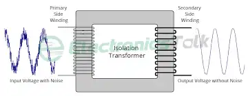
Figure 01: Isolation Transformer
There are several methods used to measure winding capacitance, each with its own guiding principles and factors. Among the most popular methods are:
1. Bridge Method
The bridge method involves balancing the capacitance of the winding under test against a known capacitance. The Schering bridge configuration is often used for this purpose.
It is named after its inventor, Ernst Werner von Siemens, who introduced this method in the late 19th century. The Schering Bridge is particularly useful for measuring capacitances that are relatively small and in the range of a few picofarads to a few microfarads.
The Schering Bridge method compares unknown capacitance to known reference capacitance using a bridge circuit. A balanced bridge circuit equals the ratio of the reference capacitance to the unknown capacitance, resulting in a zero or minimum output. The circuit consists of four arms: two fixed capacitors, a variable resistor, and a variable capacitor. By adjusting the variable resistor and capacitor, the bridge is balanced, allowing for the calculation of unknown capacitance. The formula for calculating the unknown capacitance:
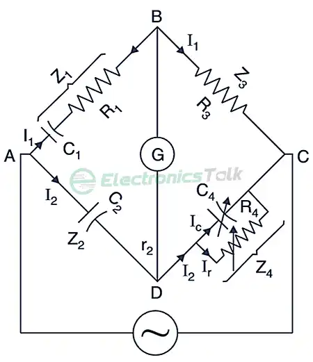

Where:
- Cx is the unknown capacitance
- Cr is the reference capacitance
- R3 is the resistance in the arm containing the variable resistor
- R4 is the resistance in the arm containing the variable capacitor
The Schering Bridge method assumes ideal components and stray capacitance and inductance in circuits. However, practical scenarios may not be accurate, so careful consideration is needed to minimize stray elements and ensure accurate measurement results. This technique is widely used in high-voltage equipment industries for accurate measurement of small capacitance values.
2. Impulse Method
The impulse technique relies on how the winding reacts to an abrupt alteration in voltage. A voltage pulse with a rapid rise time is administered to the winding, and the resultant pattern of current is documented.
Through examination of both the current pattern and the administered voltage, the capacitance can be ascertained. This approach is especially valuable when dealing with high-voltage windings.
3. Resonance Method
In the resonance method, the winding is connected in parallel with an external inductor, forming a resonant circuit. The circuit is excited with a variable frequency voltage source. At the resonant frequency, the impedance of the circuit becomes minimum, and the phase angle between current and voltage approaches zero.
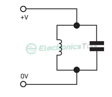
By measuring the resonant frequency and the impedance, the winding capacitance can be calculated.
4. Frequency Response Analysis (FRA)
Frequency Response Analysis (FRA) encompasses the process of varying frequencies across a spectrum while gauging the impedance of the winding at each distinct frequency point. The resultant graph depicting impedance against frequency offers insights into the winding capacitance.
This technique is capable of detecting even slight alterations in capacitance brought about by factors like winding distortion or degradation of insulation materials.
Frequently Asked Questions and Answers (FAQs)
How is winding capacitance measured in a transformer or an inductor?
Typically, a capacitance meter or an LCR meter (Inductance, Capacitance, and Resistance meter) is used to measure the winding capacitance in a transformer or an inductor. While keeping the other windings open-circuited, a tiny AC voltage is applied to one winding during the procedure.
The winding capacitance may be determined from the current flow and phase shift that arise from the applied voltage and current. The measured capacitance can be used to evaluate the parasitic capacitance that may have an impact on the component’s overall performance.
How does the dielectric material of insulation affect winding capacitance?
The amount of winding capacitance is significantly influenced by the insulating material used between the windings. greater capacitance values are produced by materials with greater dielectric constants (ε), as these materials can store more electric charge per unit of surface area.
To balance aspects like insulation strength, capacitance, and overall circuit performance, engineers choose insulation materials depending on their dielectric qualities.
Can winding capacitance impact the performance of high-frequency circuits?
Yes, the performance of high-frequency circuits may be considerably impacted by winding capacitance. It may produce undesirable coupling, which might cause crosstalk and signal interference.
Additionally, it may result in unintended resonance circuits that alter the component’s and the circuit’s overall frequency response. Design engineers may minimize these impacts and enhance the functionality of circuits by measuring and taking winding capacitance into account.
To Conclude
Winding capacitance measurement is crucial for evaluating and maintaining electrical system performance. Techniques like bridge, impulse, resonance, and frequency response analysis assess winding capacitance, ensuring the safe and efficient operation of electrical devices in design, manufacturing, condition monitoring, and diagnostics.
![[Explained] Can Resistors Change Value Over Time?](https://www.electronicstalk.org/wp-content/uploads/2023/08/Can-Resistors-Change-Value-Over-Time-768x431.webp)