How Do You Convert 240V AC to 240V DC (Step Guide)
How do you convert 240V AC to 240V DC? Rectify the alternating current using diodes, smooth the choppy output through a capacitor, then step whatever is left down to the target voltage. Here comes the part most tutorials skip. Rectified 240V AC is not 240V DC. Peak sits near 339 volts, so any honest design has to pull that figure back before earning the label.
Last updated: August 13, 2026. Rewrote as a step-by-step procedure, added the 339V peak reality, safety warnings, and internal links.
I have built a handful of these supplies on the bench, and the same misconception trips folks up every single time. They assume 240 volts in equals 240 volts out. Physics disagrees. Hard. Let me walk you through what actually happens, stage by stage.
How Do You Convert 240V AC to 240V DC in Four Stages
The full chain has four jobs. Each one fixes a specific problem the stage before leaves behind.
- Rectify. Force current to flow one direction only.
- Smooth. Fill in the gaps with a storage capacitor.
- Regulate. Lock the output to a fixed rail.
- Protect. Add fusing plus bleed resistors so the board is safe to touch.
Skip any one and you get something either unsafe, unstable, or wrong. So how do you convert 240V AC to 240V DC without those pitfalls? Follow the stages in order.
Step 1: Rectification
Rectification is the first real conversion. A rectifier lets current pass one way and blocks the other, which turns a swinging AC waveform into a bumpy DC one. Two options exist.
A half-wave rectifier uses a single diode. It passes the positive half of every cycle and dumps the negative half. Simple. Cheap. Wasteful. Roughly 50 percent of the waveform gets binned, and the output pulses hard enough that any decent load will complain. I almost never reach for it on a real supply. Skip it.
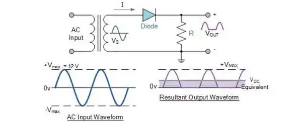
Image 1: Half Wave Rectifier
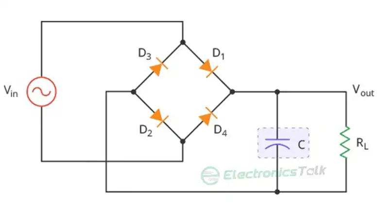
A full-wave bridge rectifier uses four diodes and flips the negative half up rather than tossing it. Both halves now do useful work. Ripple drops by more than half compared with the half-wave version, and the resulting signal is far easier to smooth. This is my default. If you are picking parts, mind the diode ratings, because rectifier diodes run hot under load. I covered that failure mode in why diodes overheat, and it earns a quick read before choosing a part number.

Image 2: Full Wave Rectifier
One more note on diode choice. A 1N4007 handles 1000V and about an amp, which is plenty for small draws, but heavier current demands a beefier part. The tradeoffs between common rectifier diodes matter more here than most builders expect.
Step 2: Smoothing With a Capacitor Filter
The rectified signal still pulses. A capacitor-input filter fixes that. The cap charges near the top of each pulse, then dumps its stored energy into the load during gaps between pulses. Dips shrink. The line flattens.
Here comes the surprise. That smoothing cap charges to the peak of the AC waveform, not the RMS reading on your meter. Peak runs about 1.4 times the RMS figure. For 240V AC that works out to roughly 339 volts across the plates. Size the part properly and you can hold ripple below 5 percent. But glance at your meter now. It reads 339, not 240.

Image 3: Capacitor Input Filter
Step 3: Regulation Down to 240V DC
This is the stage older textbooks gloss over. You have about 339 volts. You want 240. Something must remove the difference.
Two options are on the table:
- A linear regulator burns the extra voltage as heat. At this power level, brutal. Dropping 100 volts across a pass element can waste 30 percent or more of your power as thermal loss, so you would need a serious heatsink. Small linear parts like the LM7805 exist for low-voltage rails, not for a mains-level bus.
- A switching regulator, such as a buck converter, chops the input at high frequency and steps it down with far less waste. Efficiency above 90 percent is normal. For a 240V DC output, this is the sensible route.
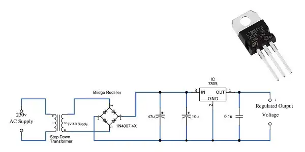
Image 4: Voltage Regulator Circuit
If you want a worked example of stepping one DC rail down to another, the same idea appears small-scale in dropping 24V to 5V. The physics scales; the danger does not.
Step 4: Protection and Safety
Do not skip this. Both 240V AC and the 339V rail can kill you, and a charged filter cap stays lethal long after you pull the plug and wander off for coffee. I fit a fuse on the input. I add a bleed resistor across the main cap so it drains within a minute of power-off. Then I probe with a meter before touching anything. Every time. No exceptions.
How I Do It on the Bench
When I build one of these, I never trust the input to be exactly what the label promises. Mains sags. Mains swells. So I give the regulator headroom, verify peak on a scope, and load-test the rail before believing any figure printed on a schematic. If you have not measured the real DC voltage under load, you do not know it yet. Guessing pops parts. That habit has saved me from more than one dead cap and a plume of smoke.
A quick reality check on the goal itself: most people asking this question really want a stable DC supply, and the exact figure of 240V DC is negotiable. If your load tolerates a range, a well-filtered bridge output may be close enough without any regulator at all. Wiring mains-level current into the wrong device brings its own hazard, the same way feeding a 220V heater from a 110V line causes trouble. Know your load first.
Frequently Asked Questions
How do you convert 240V AC to 240V DC safely at home?
Honestly, if you have to ask, get help. Mains-level DC is lethal and the filter cap holds a charge after power-off. Use a fused input, a bleed resistor, and an insulated enclosure, and measure before you touch. I would not treat this as a beginner project.
Does rectifying 240V AC give you 240V DC?
Nope. A smoothing cap charges to the peak, which is roughly 1.4 times the RMS value, so you land near 339V DC. Getting a true 240V DC output takes a regulator to step that peak back down.
Can the same process convert other voltage levels?
Yes. Rectify, smooth, and regulate works at any level once you adjust the component ratings. The peak-versus-RMS math still applies, so always design around the peak, not the number on your meter.
Why convert AC to DC in the first place?
DC can be stored in batteries and AC cannot, and almost every digital device runs on DC internally. That is why nearly every charger and power brick you own is doing this conversion.
Is a switching supply better than a linear one here?
For a high-voltage rail, yes. A switching regulator runs cool and efficient, while a linear part would waste a large share of the power as thermal loss and demand a heavy sink. At 240V the switching approach wins on both counts.
Related Reading
Bottom Line
How do you convert 240V AC to 240V DC? Rectify the mains with a full-wave bridge, smooth it via a capacitor, then step the roughly 339V peak down to a steady 240V DC. The trap is assuming the rectified signal already equals the input; it does not, and the peak-versus-RMS math is what separates a working supply from a dangerous guess. Respect the voltage, fit protection, and measure under load before trusting any figure.