Standard Lead Spacing for Capacitors: The Full Guide
The standard lead spacing for capacitors is 5mm for small film radial parts. That is the number I reach for first on the bench. Bigger film and electrolytic bodies climb a fixed ladder of pitches: 2.5, 5, 7.5, 10, 15, 22.5, and 27.5mm. Match it. Buy the part. Done.

Last updated: August 13, 2026 — added a pitch table, a fitting checklist, a bench workflow, and a full FAQ.
Lead spacing is the distance between the two wire leads where they leave the body of a through-hole capacitor. Engineers also call it the pitch. I treat it as a mechanical number, not an electrical one. It has to line up with the hole spacing you drilled into your PCB. Get it wrong and the part will not drop in cleanly, and you will spend the next ten minutes fighting bent leads.
Here is how I think about it. When I open a datasheet, pitch is the first line I read. Why? A part I cannot fit is useless, however pretty its numbers. Let me walk you through the values, how I match them, and the mistakes I learned to dodge.
What Is the Standard Lead Spacing for Capacitors?
There is no single value. It is a short list of preferred pitches, and makers stick to them so parts stay swappable across brands. Global standards come from the IPC (Institute for Printed Circuits) and the wider metric preferred-number system, which quietly governs almost every through-hole footprint you will ever solder. The logic is simple. Fewer pitches, fewer footprints. That means cheaper tooling and easier sourcing.

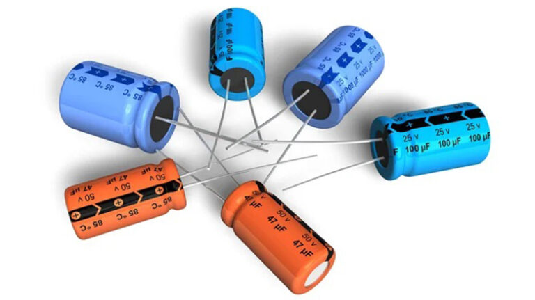
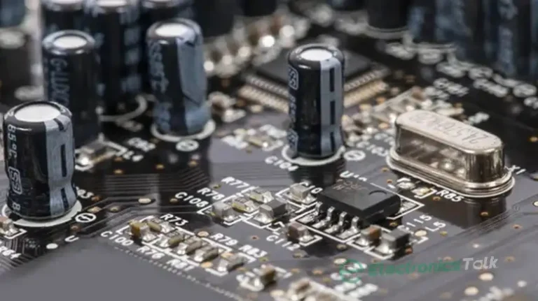
Figure: Capacitors of various lead spacing.
Here are the pitches you will actually meet, and the capacitor families that use them:
| Lead pitch | Typical capacitor family | Where you see it |
|---|---|---|
| 2.5 mm | Small ceramic disc, tiny film | Signal and decoupling caps |
| 5.0 mm | Small film radial, small electrolytics | The everyday default |
| 7.5 mm | Mid film, larger electrolytics | Power filtering |
| 10 mm | Box film, bulk electrolytics | Supply rails |
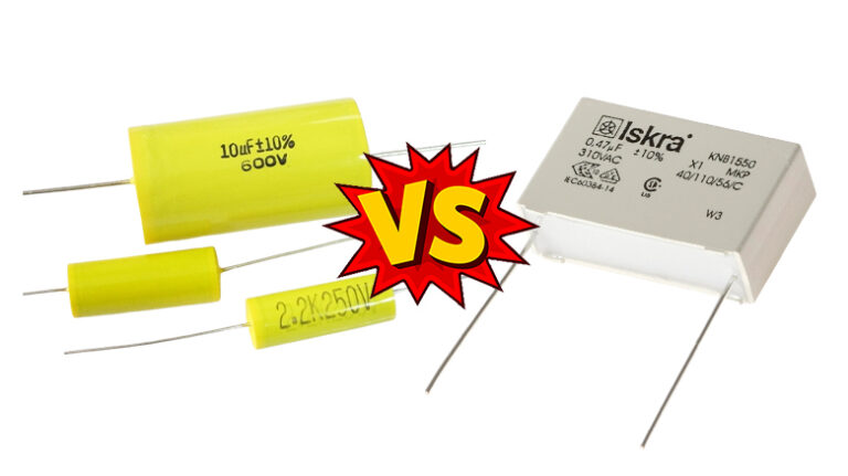
| 15 mm | Large box film | Motor run, snubbers |
| 22.5–27.5 mm | High-voltage and high-current film | Mains, PFC stages |
Notice the jumps. They are not random. Each step roughly doubles the body volume the part can carry, so a fatter capacitance or a taller voltage rating lands on a wider pitch. For a given value and rating, a maker usually offers a small matrix of packages. You pick the one that suits your layout.
Say the pitch does not match your board. Then you bend the leads. Do it gently. Bending absorbs the mismatch and spares the part from strain later. One rule I never break: don’t bend right at the body. Leave a few millimeters of straight wire first, or you risk cracking the seal where the lead enters the case. I ruined two tantalum caps that way early on, so trust me on this.
What Are the Leads on a Capacitor?
A polarized capacitor has two leads, positive and negative, and telling them apart matters. Get it backwards on an electrolytic and it can vent or pop. I have heard one go off across a lab bench, and you don’t forget the smell.

Figure: Leads of Capacitor.
Two quick ways to read the polarity:
- Check the body marking. A stripe with minus signs points to the negative lead. On the can, the shorter side of the stripe is the negative terminal.
- Check the lead length. Straight from the factory, the longer lead is positive and the shorter lead is negative. Cut them and you lose this clue, so read the marking first.
Film and ceramic capacitors are non-polarized. Their two leads are interchangeable, so orientation is a non-issue and only the pitch matters there.
How to Pick the Right Lead Spacing
Here is the exact order I work through when I am matching a part to a board:
- Measure the hole spacing on your PCB. Center to center, with calipers. Write it down.
- Match it to a standard pitch. Round to the nearest value in the table above. Boards are almost always laid out on these pitches.
- Check the capacitance and voltage you need. Pull the datasheet and find the package that carries both.
- Confirm the body diameter clears its neighbors. A 10mm pitch part can still have a fat body that fouls a nearby connector.
- Buy that exact package. Do not eyeball it. A 5mm part will not sit in 7.5mm holes without splaying the leads.
Makers publish lead-spacing guides and dimensional drawings for every series. I read them before I order, every time. The size of a capacitor’s body and its pitch are tied together, so when you check one without the other, it usually bites you.
Do You Need to Extend or Bend Capacitor Leads?
Sometimes. If the only part in stock has a smaller pitch than your board, you bend the leads outward to reach the holes. If a lead is too short to bend safely, you extend it. Short, stubby leads on some ceramic caps leave me no room to work, so I treat extension as the fallback, not the first move.
Keep the added length small. Long leads add series inductance, and that chokes high-frequency signals. Roughly 1mm of wire adds about 1nH, enough to matter in a switcher or an RF stage. There, I keep everything as short as I can, ideally under a few millimeters. At low frequency? You’ll never notice.
How Do You Extend a Capacitor Lead?

Step 1: Cut two short pieces of tinned copper wire, one per lead.
Step 2: Hold each wire against the capacitor’s own lead, heat the joint with your iron, and flow solder through it. Sleeve the joint with heat-shrink so the two extensions cannot touch. Keep the extension short for the reason above.
Does the Physical Size of a Capacitor Matter?
Electrically, mostly no. Two parts of equal value and equal rating behave alike, fat body or slim. One exception shows up in switching supplies, where low ESR capacitors are needed and body size tracks the internal foil area that sets ESR. There, the package does shift the numbers.
What always matters is the fit. Pitch decides whether the part drops onto your board. Voltage headroom decides whether it survives your rail. The rest is secondary. If you want the deeper version of the size question, I covered whether physical dimensions change the electrical result in its own post, and the tolerance side of the same coin lives in this guide on why the tolerance band matters.
Frequently Asked Questions
What is the most common capacitor lead spacing?
5mm. It is the default pitch for small film radial capacitors and many small electrolytics, and it is the first value most boards are laid out for.
Is capacitor lead spacing the same as pitch?
Yes. Pitch and lead spacing both mean the center-to-center distance between the two leads. The words are interchangeable on a datasheet.
Can I bend capacitor leads to fit a wider footprint?
Yes, carefully. Bend a few millimeters away from the body, never at the case, so the seal stays intact. Splaying wires to reach a broader footprint is common and safe when done gently.
Does lead spacing affect the capacitor’s electrical value?
No. Lead spacing is a mechanical dimension for fitting the part to holes. It does not change capacitance, voltage rating, or tolerance.
What lead spacing do large film capacitors use?
Big box film capacitors step up to 15, 22.5, and 27.5mm pitches. Mains-rated and power-factor parts sit at the wide end because they carry more voltage and current.
Do smaller leads limit high-frequency performance?
Yes. Longer wires add series inductance, roughly 1nH per millimeter, which throttles a part’s ability to pass fast signals. Keep them short in RF and switching circuits.
Related Reading
Bottom Line
The standard lead spacing for capacitors is a fixed ladder, and 5mm is the value you meet most for small film radial parts. Larger and higher-voltage parts climb to 7.5, 10, 15, 22.5, and 27.5mm. The pitch is purely mechanical, so match it to your board’s hole spacing, confirm the voltage and capacitance on the datasheet, and buy that exact package.