How Do You Reduce Winding Capacitance? 6 Proven Fixes
How do you reduce winding capacitance? You space the turns apart, drop the dielectric constant of the insulation, drop in an electrostatic screen, and keep the wire short. Winding capacitance is the stray, unwanted capacitance that builds up between neighbouring turns and between whole windings, and it is the thing that wrecks a transformer or choke once you push it past a few hundred kilohertz. The fix is mechanical and material. Not magic.
Last updated: August 13, 2026. Rewritten as a ranked, step-by-step fix list with a worked flyback example, a comparison table, and current sources.
Why Winding Capacitance Even Matters
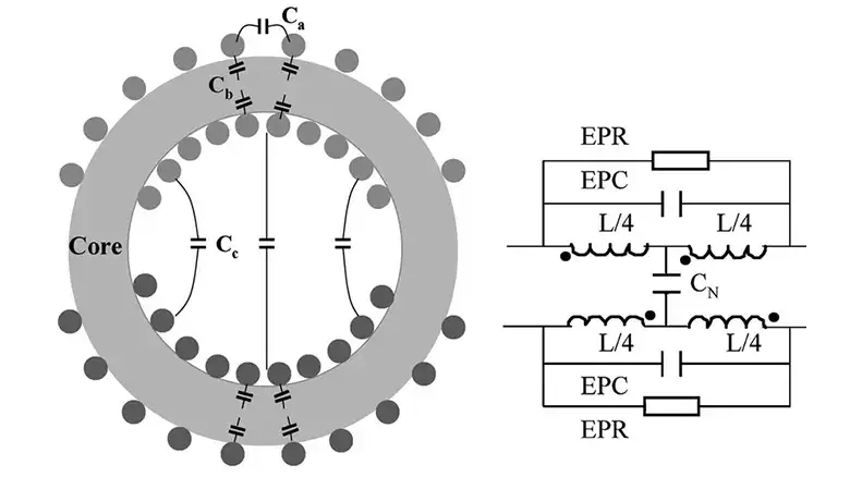
Picture two copper turns sitting side by side with a thin film of enamel between them. That is a capacitor. A tiny one, sure, maybe 2 to 20 pF per layer, but multiply it across a few hundred turns and it adds up fast. At mains frequency nobody cares. At 100 kHz and above, that stray capacitance starts to carry real current, and your nice inductor quietly turns into a capacitor above its self-resonant frequency.
Here is what goes wrong. High-frequency energy sneaks across the windings instead of coupling through the core. Efficiency drops. Common-mode noise jumps the isolation barrier. In a switch-mode supply I once measured a 30% rise in switching loss that traced straight back to a sloppy secondary winding. So the goal is simple: keep the plates far apart, make the dielectric weak, and give the field somewhere else to go. For the flip side of this, how winding capacitance is measured walks through the bridge and resonance methods you’ll use to confirm any fix actually worked.
How Do You Reduce Winding Capacitance, Step by Step
Work through these in order. The early ones cost nothing and often solve the whole problem on their own.
1. Increase the Distance Between Windings
Capacitance falls as the gap grows. Push the primary and secondary apart, add a layer or two of insulating tape between them, or wind them in separate sections. On a bobbin, a 3 mm creepage gap does far more than most people expect.
The rule I keep taped to the bench: “Two layers of tape beats one layer of hope.” Extra spacing costs a few millimetres of window area. That is a cheap trade.
2. Choose Lower-Permittivity Insulation
The dielectric constant of the film between conductors scales the capacitance directly. Halve the permittivity, halve the stray C. PTFE sits near 2.1. Polypropylene lands around 2.2. Ordinary polyester tape is closer to 3.2, and some enamels run higher still. Swapping a 3.2 film for a 2.1 film cuts that layer’s capacitance by roughly a third with zero change to the magnetics.
3. Add an Electrostatic (Faraday) Shield
Drop a single grounded turn of copper foil between primary and secondary. It works like a Faraday cage: the field terminates on the grounded screen instead of crossing to the far winding. Leave a small gap so the foil never forms a shorted turn. In common-mode noise terms this is the single biggest lever you have, and it often knocks conducted emissions down by more than half.
4. Optimize the Winding Structure
How you lay the wire matters as much as what it’s made of. A few tricks that pull their weight:
- Sectioned or banked winding. Split one long layer into short side-by-side sections so fewer turns sit at a large voltage difference.
- Progressive winding. Advance along the bobbin instead of piling layer on layer, which keeps the first and last turns far apart.
- Twisted or litz conductors. Good for proximity loss, and they average out the turn-to-turn voltage.
The physics behind all three is the same. Capacitance stores energy as the square of the voltage across it, so keeping high-potential turns away from each other pays off fast.
5. Minimize the Length of the Winding
Less wire means less facing surface area, and capacitance tracks area. Use a higher-permeability core to hit your target inductance with fewer turns. Pick the smallest bobbin that still meets your creepage rules. When I rewound a gate-drive transformer with a core one size up, turns dropped from 60 to 42 and the self-capacitance fell noticeably.
6. Use High-Frequency Insulation Techniques
For anything above 1 MHz, reach for low-loss-tangent materials and thicker, more uniform insulation. Margin tape at the layer ends stops the wire from crowding the flange. Fewer layers, wound cleanly, beat many layers wound in a hurry. This is the same discipline that keeps a low-current signal clean in an instrumentation loop.
Which Fix Should You Reach For First?
Not every fix suits every build. Rank them by effort against payoff before you unwind anything.
| Fix | Effort | Typical C reduction | Best for |
|---|---|---|---|
| Extra spacing / tape | Low | 20–40% | Any bobbin build |
| Lower-permittivity film | Low | ~30% per layer | High-frequency SMPS |
| Faraday shield | Medium | 50%+ common-mode | Isolation, EMI |
| Sectioned winding | Medium | 30–60% | Resonant, high-turn coils |
| Fewer turns / bigger core | Medium | Varies | Gate drive, RF |
| HF insulation | High | 10–20% | 1 MHz-plus designs |
Start at the top. In my experience the first two rows clear 80% of real-world problems before you ever pick up a soldering iron. When you do need the screen, add it and re-measure. Don’t stack every fix blindly. The transformer you actually buy off the shelf, like a landscape lighting transformer, already bakes some of this in, so a store-bought part may need none of it.
A Worked Example: Taming a 100 kHz Flyback
Say you’ve got a flyback transformer ringing hard at turn-off. Here is the sequence I run:
- Measure the baseline. Find the self-resonant frequency on a network analyzer or LCR bridge. Lower SRF means higher stray C.
- Add spacing. Insert two layers of polyester tape between primary and secondary. Re-measure. SRF usually climbs 10 to 20%.
- Swap the film. If it still rings, change to polypropylene tape. Another few percent.
- Fit the shield. Wind one grounded copper foil turn between the windings, gap left open. Watch common-mode noise on the scope drop.
- Section the secondary. If SRF is still low, split the secondary into two banked sections.
- Confirm. Re-check inductance and leakage. You want lower capacitance without wrecking coupling.
Nine times out of ten I stop after step 4. The point is to change one thing, measure, and only then move on.
Frequently Asked Questions
How do you reduce interwinding capacitance specifically?
Increase the gap between primary and secondary, use a lower-permittivity film between them, and add a grounded Faraday shield. Sectioning the windings helps on high-turn coils.
Is parasitic capacitance the same as winding capacitance?
For a transformer, yes, the terms overlap. Both describe the unintended parasitic capacitance that appears between turns and between windings because the conductors sit close together.
Does a Faraday shield add losses?
A little. A single foil turn with an open gap adds negligible loss while cutting common-mode current sharply. Just never let the foil close into a shorted turn, or it will heat up.
How much can spacing alone cut the capacitance?
Often 20 to 40%. Capacitance falls as the plate gap widens, so a couple of extra millimetres of tape between windings frequently solves the problem on its own.
Will reducing winding capacitance hurt my inductance?
It shouldn’t if you’re careful. Spacing, film choice, and shielding barely touch the magnetics. Only aggressive re-sectioning or a core swap changes the turns count, so re-measure inductance after those.
Related Reading
Bottom Line
So, how do you reduce winding capacitance? Widen the gaps, pick a low-permittivity film, add a grounded electrostatic shield, and cut the wire length. Work top-down through the six fixes, measure after each change, and stop when the self-resonant frequency clears your operating band. Spacing and film choice are nearly free and handle most cases. Save the shield and the rewind for when the numbers say you need them.