Difference Between Op Amp and Transconductance Amplifier
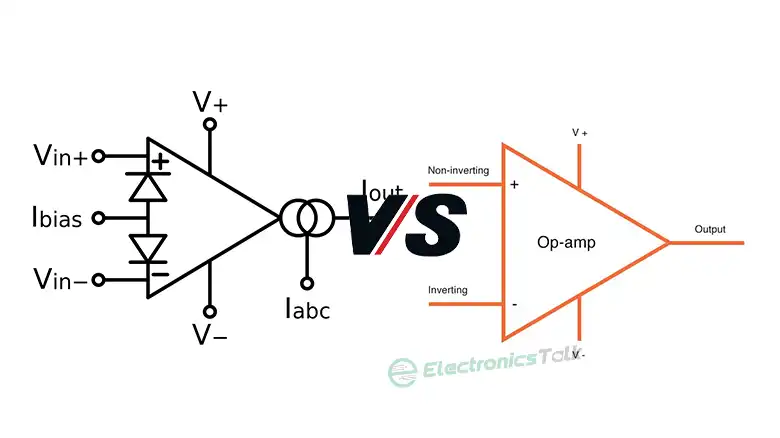
So what is the difference between op amp and transconductance amplifier chips? Short version: output. An op-amp reads the voltage gap across its two inputs and hands you a much larger voltage back. A transconductance amplifier, better known as an OTA, reads that same voltage but delivers a proportional current instead. Voltage out versus current out. One tiny choice. Everything else follows.
Last updated: August 13, 2026. I rebuilt this as a side-by-side head-to-head, added a fresh spec table, a plain verdict, and a short bench note.
I’ve reached for both parts on real boards. In my experience, treating an OTA like some drop-in replacement for an op-amp is the classic slip-up. It isn’t one. When I first dropped one into an active filter, the gain drifted the second my bias current wandered. Painful. So let me sketch out where each chip wins, drop a spec table, then give you a clear pick you can act on this afternoon without second-guessing yourself.
What Is the Difference Between Op Amp and Transconductance Amplifier, Side by Side
The core idea sounds tiny. It’s not. An op-amp behaves as a voltage-in, voltage-out block with enormous open-loop gain, tamed by a network of feedback resistors. An OTA behaves as a voltage-in, current-out block whose gain rides on a control current. Never resistors. Here is the whole picture in one table.
| Trait | Op-amp | Transconductance amplifier (OTA) |
|---|---|---|
| Output | A voltage | A current |
| Gain model | Vout = Aol × (V+ minus V−) | Iout = gm × Vin |
| What sets the gain | External resistors | A bias or control current |
| Open-loop gain | Often above 100,000 | Set by gm, tunable live |
| Input impedance | Very high, above 1 MΩ | Lower, and it varies |
| Output impedance | Very low | High, behaves as a current source |
| Typical bandwidth | A few MHz for jellybean parts | Up to the GHz range in RF designs |
| Linear range | Wide | Narrow without help |
| Price | Well under $1 in bulk | About $2 for common dual OTAs |
| Best at | Buffering, gain, signal conditioning | Tunable gain, filters, RF, mixers |
The 741 op-amp has stayed in production for over 40 years, and that longevity alone tells you how forgiving the voltage-out model really is when you throw messy real-world signals at it. Wire two resistors. Get a gain. Done. The OTA asks more of you, and it rewards you with something the op-amp cannot pull off: gain you can sweep on the fly.
The op-amp: a voltage machine
Picture an op-amp as a lever for voltage. It watches the gap between the plus and minus pins, multiplies that gap by a huge number, then swings its output until feedback drags the inputs back level. That negative feedback loop is the whole trick. Wrap the right resistors around it. Your gain becomes stable. Flat. Boring, in the best way.
Because the output acts like a stiff voltage source, an op-amp buffers beautifully. It shrugs off load changes. No flinching. That’s why you spot them everywhere: audio preamps, sensor front ends, and the input stages of nearly every ADC or DAC on the market. If you’ve ever worried whether a chip will drive the next block cleanly, an op-amp is usually the safe answer. For the fussy edge case of stability at unity gain, I run through the full checklist in this guide on checking whether an op-amp is unity-gain stable.
The transconductance amplifier: a current machine
An OTA flips the job on its head. Feed it a tiny voltage, and it pushes out a proportional current. That proportionality constant is gm, the transconductance, and here is the important bit: you steer gm with a bias current. Twist the knob. Your gain moves live. This “voltage in, current out” behaviour turns the chip into a voltage-controlled current source.
That’s why OTAs live inside voltage-controlled filters, automatic gain loops, and RF mixer stages. The same gm term shows up in raw MOSFET math too. If you’d like the underlying formula, my write-up on the transconductance term Kn walks through where gm comes from at the device level.
Where Each Chip Wins
Reach for an op-amp when:
- You need a clean, buffered voltage output.
- You want gain set once by resistors, then left alone.
- Your signal sits below a few MHz.
- You value a wide, forgiving linear range.
- You want a component that costs pennies and simply works.
Reach for a transconductance amplifier when:
- You need to shift the gain while the circuit runs.
- You are building a tunable or voltage-controlled filter.
- You are up in RF territory, into the GHz band.
- You can gate the bias current down and shave idle power, sometimes by 90%.
- You need a current output feeding into a low-impedance node.
How I Pick Between Them on the Bench
When a fresh design lands on my desk, I run the same short decision, and it takes roughly 10 minutes:
- Ask what the next stage wants. Voltage? Lean op-amp. Current, or a summing node? Lean OTA.
- Ask if the gain must shift during operation. Fixed gain points at the op-amp. Live, sweepable gain points at the OTA.
- Check the frequency. Below a few MHz, either works, so grab the cheaper op-amp. Well into the GHz band, the OTA usually wins.
- Check linearity needs. Op-amps hold a wide linear window for free. OTAs stay clean only across a small input swing, roughly where distortion sits under 1%, unless you add local feedback.
- Check the power budget. If idle draw matters, the OTA lets you throttle its bias current down.
That’s it. Nine times out of ten, the answer becomes obvious by step two, and the remaining ten percent usually boils down to a power-budget corner case where you either need the OTA’s throttled bias or you don’t.
Don’t force an OTA into an op-amp socket. And please don’t expect an op-amp to sweep its gain on command. Cousins. Not twins. If you’d like to see how two parts inside the same family can still behave very differently, the same lesson pops up when you compare two classic op-amps head to head.
Frequently Asked Questions
Is an OTA just an op-amp with a current output?
No. It shares the two-input front end, sure, but the OTA delivers a current governed by gm, and you tune that gm through a bias current. An op-amp delivers a voltage and leans on resistor feedback. Their control model is what really pulls them apart.
Which one is more power-efficient?
The OTA, usually. You can gate its bias current low, which slashes idle draw sharply, sometimes by around 90% in standby. A general-purpose op-amp burns a steady quiescent current whether a signal shows up or not.
Can I replace an op-amp with a transconductance amplifier?
Rarely, and never as a straight swap. Their output impedances are opposite: low for the op-amp, high for the OTA. Unless the surrounding circuit already expects a current source, dropping an OTA in will wreck the biasing and mess up the gain.
Why do RF designs prefer the transconductance amplifier?
Speed, plus tunability. An OTA can work well into the GHz range, far past the few-MHz ceiling of a jellybean op-amp. Its gain also tracks a control current, which is gold for mixers and gain-loop control.
Are op-amps cheaper than OTAs?
Generally, yes. A basic op-amp lands well under $1 in volume, while common dual OTAs sit around $2. For plain gain or buffering, the op-amp wins as the frugal pick.
Which chip handles higher input impedance better?
The op-amp. Modern CMOS parts top 1 TΩ at their inputs, ideal for high-impedance sensor front ends. An OTA presents a lower, drifting input, so it rarely suits raw sensor pickup without a buffer stage ahead of it.
Related Reading
Bottom Line
The difference between an op-amp and a transconductance amplifier boils down to one word: output. The op-amp hands you a voltage, tamed by resistors, and it stays the cheap, forgiving default for gain and buffering. The OTA hands you a current, steered by a bias, and it earns its keep the moment you need live gain control, RF speed, or lower idle draw. Match the output to what the next stage needs, and the choice writes itself. For deeper theory, the Wikipedia entries on the operational amplifier and the operational transconductance amplifier hold up well, and Texas Instruments still publishes the classic LM13700 dual OTA datasheet.